Teleperception
- Technology for TBS - extensions
The technology for
a TBS-Teleperception-System consists of the following sections:
the Visual Section: transmitting a stereoscopic picture from WashBot to Operating Station and Brainwashing Station
the Audio Section : transmitting the audial information from the Washbots microphone to the Operating Station and Brainwashing Station
the Head Position Tracking : transmitting the Brainwashing Operator's viewing direction to the Washbot
the Cam Positioning: for adjusting the Cameras to the Operators viewing direction
the Washbot Landscape Tracking: transmiting the 3D-characteristics of the landscape surface to the Operating Station
the Operating Station Movement Control: moves the hydraulic systems of the VR-chair according to the Landscape characteristics the Washbot drives through.
Visual
Section
There are different ways, how
stereoscopy in the human eyes can be pretended. In all cases images
of a scene with two, in the viewing distance and angle positioned
cameras, are created and these are joined over a certain technique to
one sinal or one image.
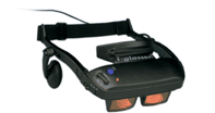
The i-glasses manufactured by the
company virtual-io operate in the "interlaced mode" i.e.
they divide the Composit PAL (or NTSC) signal into even and odd
field, whereby in every case one field is shown the left and the
other field the right eye over an own LCD.
in the visual area, the following action have to be taken:
- to position two ccd cameras in the viewing distance and in an select angle
- to mix the signals output of the cameras into interlaced video
- this signal has to be transmitted
- if you want to mix two composit signals by field into one, the signals must
be absolutely synchronous.
if one camera is ready with one field, the second camera
must be ready with this field, too.
- a flicker-free switching between the individual signals is provided by short
switching times
- it would be an advantage to know when which field is sent. It could be e.g.
that the field of
the right camera is transmitted on the left eye.
Implementation
of the visual section:
the synchronisation of light ccd
cameras can be done when deactivating the oszillator of one camera
and feeding it with the oszillator frequency of the other camera. If
the cameras are identically constructed, one can assume the two
cameras record absolutely synchronously the same field. Over a
Synchronisationsseperator (we decided for the
LM1881N of National Semiconductors)
one receives the vertical synchonisation signal from a composit
signal (speak field synchronisation signal) and the odd/even signal.
then you have to switch between the two signals via a video
switch(TEA2014 of Thomson) to mix the two composit signals to one.
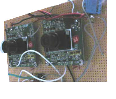
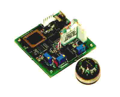
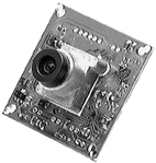
Stereoscopic camera transmission unit, mountable on washbot (teleperception
robot)
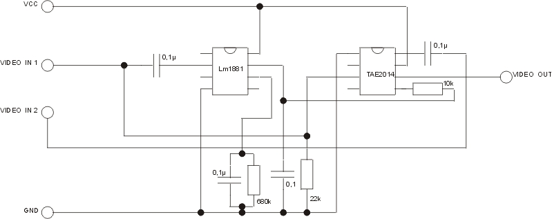
electronic sceme for mixing up two cam-signals into one
stereo signal
Audio section
The audio signal is received from the washbot via giga-link-radio
receiver. The signal is directly fed into the i-glassed audio-input (stereo).
Movement Tracking
Human
movement tracking systems can be classified as inside-in, inside-out and outside-in
systems.
Inside-in
systems are defined as those which employ sensor(s) and source(s) that are both
on the body (e.g. a glove with piezo-resistive flex sensors). The sensors generally
have small form-factors and are therefore especially suitable for tracking small
body parts. Whilst these systems allow for capture of any body movement and
allow for an unlimited workspace, they are also considered obtrusive and generally
do not provide 3D world-based information.
Inside-out systems employ sensor(s) on the body that sense artificial external source(s) (e.g. a coil moving in a externally generated electromagnetic field), or natural external source(s) (e.g. a mechanical head tracker using a wall or ceiling as a reference or an accelerometer moving in the earth's gravitational field). Although these systems provide 3D world-based information, their workspace and accuracy is generally limited due to use of the external source and their formfactor restricts use to medium and larger sized bodyparts.
Outside-in systems employ an external sensor that senses artificial source(s) or marker(s) on the body, e.g. an electro-optical system that tracks reflective markers, or natural source(s) on the body (e.g. a videocamera based system that tracks the pupil and cornea). These systems generally suffer from occlusion, and a limited workspace, but they are considered the least obtrusive. Due to the occlusion it is hard or impossible to track small bodyparts unless the workspace is severely restricted (e.g. eye movement tracking systems). The optical or image based systems require sophisticated hardware and software and are therefore expensive.
Head-Tracking and data-transmission for TBS
For the TBS, it is important to get the Head Position of
the Brainwashing Operator and to adjust the viewing direction of the WashBot-Cameras
to the right viewing angles of the Operator. The tracker that i-glasses support
operates relative to the earth's magnetic field and supplies the three absolute
angles of the tracker coordinate system to that of the earth's magnetic field.
The transfer is serial, whereby alternatively the angles either in ASCII or
as binary will be transfered. The motion control PC receives the measured angles
via a RS 232 protocol and sends the received head tracking via radio-modem to
the Washbot-avatar. On the Washbot, the viewing angles of the 3D-Cam-System
are adjusted according to the head-tracking via the servo-controller.
The Cam Positioning
The Positioning of the Cam-System on the Washbot is done via a microcontroller, that receives the Operator's Head Position via radio-modem. The microcontroller uses the RS232-serial data transmission protocol to get the angles from the modem. The two cameras on the Washbot are fixed to servos that determine the viewing direction. The microcontroller calculates appropriate servo-positions from the tracked head-position and sends the data-bytes to the servo-controller, also via RS232.
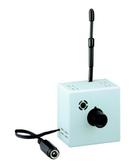
The Washbot Landscape Tracking
The Landscape Tracking is used to get information about the 3D-charakteristics of the Washbot's driving. The Mountais and raod conditions the Washbot expieriences are measured by a 3d-compass and sent to the Operating Station via radio-modem.
3d-compass measuring surface conditions
of Perceptual Landscape
The Tele-Operation-Station Movement
To get a haptic movement-feedback at the Operating Station, the 3D-Landscape information tracked by the 3D-compass of the Washbot is used to move the Operator's VR-chair via a hydraulic movement simulator. The Movement Control PC calculates the yaw/pitch/roll - angles from the transmitted compass information and effects the hydraulic system via RS232-connection.
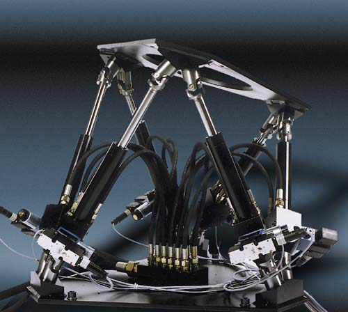
hydraulic VR-Chair-Movement
Parts-List / Prices
BrainWashing Station
EEG-measurement and feedback
*
Wave Rider EEG-amplifier
2 EEG Channels,
1 EKG, 1 GSR, RS232 communication interface,
WaveWare Software-Package, Cap, electrodes, electrode-gel
*
Pentium PC for EEG-measurement + visualisation needed: 1
2. Motion & Perception Operating
Station
VR TeleExistance Environment
* Hydraulic motion system Hydraudyne System Inc.
Payload
325kg / 700lbs
Degrees of freedom:
6
Design Payload Properties:
Weight : 325 kg (717
lbs)
Ixx :125 kgm2 (92
slug-ft2)
Iyy : 238 kgm2 (176
slug-ft2)
Izz
: 207 kgm2 (153 slug-ft2)
Actuators: Low friction
hydraulically driven
Platform shape :
Triangular
Platform size : 0,71
x 0,62 m (28" x 24")
Drive electronics
: PC based
220 VAC / 50Hz (120
VAC/ 60Hz), 0,25 kW.
Ethernet or RS232
connection.
Update rate from
30 / 50 or 60Hz.
*
I-glasses Virtual I/O-System needed:2
3D-Video-glasses, PC-VGA-interface (640x480x256),
head-motion-tracker, RS232-interface
*
Pentium PC for motion control
*
ADAM-4550 Funkmodem needed:2
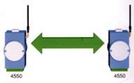
2,4 GHz Band, 100 mW, max. 200 m, RS-232 / RS-485 interface, up to 248 clients, Direct Sequence Spread Spectrum Modulation (DSSS)
bandwidth:
22 MHz (1 channel), data rate max. 115,2 kbps
handshake: Xon/Xoff,
RTS/CTS, supply: +10 VDC bis +30 VDC, max. 4 W
* Multimedia-Projector 3M MP 7630 needed:1
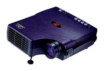
2,3 kg, 800 ANSI lumen, SVGA-mode (800 x 600 pixels)
weight 2,3 kg, DLP (B x H x T) 198 x 65 x 245 mm.
3. WashingRobot mobile Perception Unit
*
Farb- PRINT-CCD- VIDEOCAMERA 3,6 mm needed: 4
1/3" Chip 500x582 (291.000) Pixel; 0,5
Lux/F2.0; Gamma=0,45; 12 VDC; 110
mA;
Autoshutter 1/50-1/100.000, 49x49x40
mm BxHxT
*
GigaLink radio-videotransmissionset needed:5
*
EZ-COMPASS-3 / MAGNETOMETER rev-2 needed:1
Pitch / Roll / Temperature compensated
COMPASS / MAGNETOMETER system
standard RS-232 and RS-422 interfaces.
0-360 deg, continuous, 12 bit,
1 deg accuracy, pitch & roll
range: -70 - +70, 300-38400 baud, 8,N,1,
supply: 5 VDC,size 2"W x 2.5"L
x 1.0"H PCB Board
* PIC or Basic Stamp Microcontroller needed: 1
16
Digital I/O-Pins, 2048 EEPROM bytes, 136 RAM bytes,
RS232- serial programming interface,
50 MIPs, supply: 5 Vdc
* Servo-Controller-Board needed:1
8 Servo-outputs, RS232- communication input, supply: 6 Vdc
*
Lego-Mindstorms Mobile Robotics Platform needed:1
* Lego-Mindstorms Accessory-Kit needed:3
3. Perception Park / Landscape
LCD-Monitor
LCM-445 needed:10
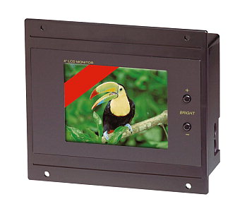
20-cm-TFT-LCD,
112 000 Pixel, PAL-TV system, cinch-video-input,
Supply: 400 mA/12
V, 410 g, (B x H x T) 149 x 134 x 40 mm
Video
Player needed:5
Materials for Basic Landscape
Bühnenelemente,
Stahl- und Holzkonstuktionen,
Beleuchtungskörper, Modelliermasse,
Bebauungsmaterialien