|
Hardware Those who look at the circuit board of the MonolithEEG and know the ModularEEG may recognise several parts. A few changes have been made to the analog signal path. The instrumentation amplifiers have been provided with active working point stabilisation at their reference inputs. The stabilisation also constitutes the first high pass filter with a low source resistance in comparison to the following low pass filter. This first low pass filter serves as a prefilter for the Sallen-Key low pass that has already been used in the ModularEEG. In the MonolithEEG the disposition to oscillate of the filter was increased to improve the stopband attenuation of the filter. The prefilter prevents clipping to the supply voltage rails of the following main filter, since it dampens the overshoot of the main filter. A weak low pass filter minimally improves the frequency response and provides the capacitors inside the ADC with sufficient charge for the conversion. The complete signal path thus provides an improved operating range and a higher slew rate at higher frequencies. Therefore, it is possible to sample at 1024Hz with a resolution of more than 10Bit. All resistors should be 1% metal film resistors. I chose 2% film capacitors for the two Sallen-Key low passes.
The MonolithEEG uses 6N137 opto-couplers which can reliably transmit data at rates above 1MBaud. This provides a simple way to higher sampling rates for the MonolithEEG
|
|
● miniaturised to 3.8 x 2.4 x 1 Inch (101 x 61 x 26mm) ● limited to 2 EEG channels each with 10 Bit resolution ● only one circuit board equipped with SMD components ● Designed for a Pactec JM 42-000 case ● USB via FTDI232 ● Supply voltage from USB ● complete galvanic isolation ● no shielding of the case necessary ● no shielding of the cables necessary ● Expansion port available on the outside ● Programming adapter integrated into the expansion port ● ATMega8 Controller by Atmel ● measurement lines connected via nine pin D-sub socket ● For experienced soldering virtuosi only ● Compatible with amonst others with ElectricGuru, BrainBay and Bioera |
|
Warning If you intend to build a MonolithEEG as described here you must proceed with extreme caution. Pay particular attention that the galvanic isolation is guaranteed at all times when the electrodes touch the body and the MonolithEEG at the same time! It is particularly important that the programming adapter does not remain inside the MonolithEEG when it is used to take measurements on a living body! This system is not certified and anybody using it in any conceivable way takes full resposibility for any consequences that may arise.
|
|
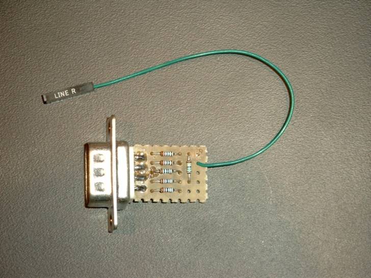
Testing procedure The testing procedure hasn't fundamentally changed compared to the ModularEEG. However, the generation of the test signal was, due to space constraints, not included on the circuit board of the MonolithEEG as was the case with the ModularEEG. Instead a custom testing plug has to be built using a nine bit D-Sub plug, six resistors, a piece of prototyping board, and a short cable. I used an old PC cable.
|
|
Programming of the Controller The MonolithEEG does not have a seperate ISP-Adapter as the ModularEEG does. the last 6 pins (11 through 16) of the extension port provide these connections. The allocation conforms exactly to the standard assignment of the 6 bit ISP-Adapter STK500 or AVR-ISP. Those who do not own a programming tool from Atmel may also use a built-your-own programming adapter such as the SP12. It is however necessary that the pin-out of the adapter conforms to the 6 bit variant. To use the fuse and lock bits in a right way here are the configuration for an ATMega8 controller: |
|
Software As mentioned above the software was expanded to handle different sampling frequencies and baud rates. The Software for the MonolithEEG hardware was modified slightly to accomodate for the push button and the status led that were used. The source code contains the potential of using the improvements for the ModularEEG. By means of conditional compilation two switches decide on whether to compile for AT90S4433, ATMega8, ModularEEG, or MonolithEEG. The MonolithEEG is always off line on power up. Thus it does not send a data stream but awaits commands. The push button starts and stops the data stream. The software supports the protocols p2 from the ModEEG and the extended version p21 by Jarek Foltynski for BioEra.
If you want to modify or expand the software you can compile the source code with avrgcc or with WinAVR . Download MonolithEEG Firmware Makefile, C-Source and Hexfile
|
|
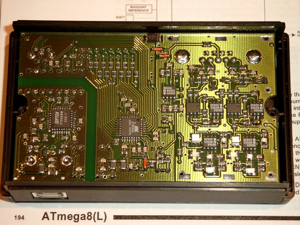
Printed Circuit Board The hardware consists of only one pcb. Controller, USB interface, reference voltage, all amplifiers, and filters are situated here. Thanks to a great number of SMD components it was possible to reduce the pcb to 2.13x3.54 inch (54x90mm) which fits into a commonly available plastic case. All components are available at Reichelt and RS-Components and can thus readily be obtained. However, the circuit board is, unlike the ModularEEG, not commercially available from Olimex in Bulgaria or any other company. I had my (empty) boards manufactured at PCB-Pool because I have had the pleasure to trade with them in the last few years and have consistently been satisfied with the provided quality. The layout was designed with Eagle 4.1x. A limited version of Eagle is available for private use.
Since I have had more pcbs manufactured than I have used some are still left. So if you wish to obtain an empty board please feel free to contact me. |
|
Connection The Controller was connected in a way that directly connects as many multi function pins to the extension port as possible. In the case of PD6 and PB0 a compromise was necessary. Both IO lines are connected via a 220 Ohm protective resistor to a pin of the expansion port. By applying the ISP-Adapter an additional PWM port (now a total of 3) became available. The MonolithEEG is thus programmable without opening the case. This is also possible with the ModularEEG if a bootloader is used. The SPI-Bus may additionally be useful for some other external hardware. The attachment of the measuring line to the MonolithEEG is uncommon. Even though this nine bit D-Sub socket features several advantages. It is shielded, cheap, gold plated, space saving, and widely available. It unites measuring lines and the DRL-line into one interface. Thus headsets may be built that relieve the user of thinking about polarity and placement of electrodes every time they are put on. Last the USB interface shall be mentioned. Besides communication lines it also provides the power for the unit. (Rechargeable) batteries or wall power supplies consequently do not have to be accounted for. . |
|
USB When using the USB-Controller FT232 the Virtual COM Port (VCP) of the FTDI has to be installed on the PC. This driver makes sure that the USB interface in the MonolithEEG is registered and can be used as a regular RS232 port in the PC.
|
|
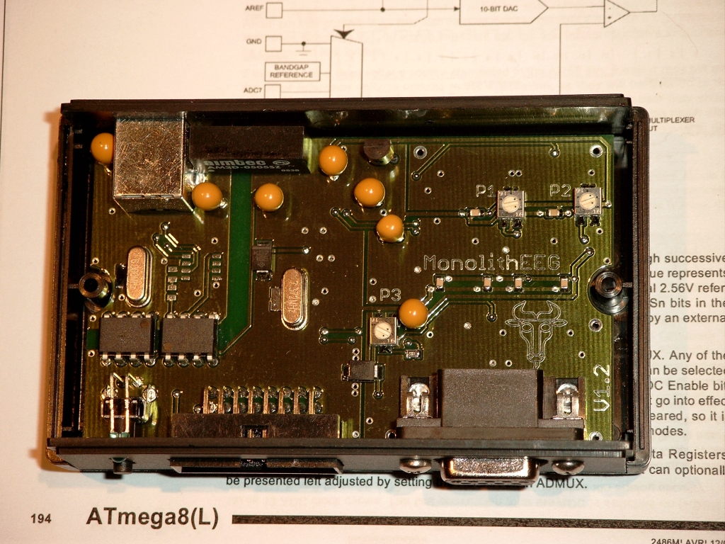
Some of you may perceive that the circuit board was soldered by hand and freed of flux by washing it (not with water). Soldering was done using a Weller WSD81 with a thick, slanted soldering tip. A regulatable soldering iron should definitely be used because the 2% capacitors of the AA filter cannot bear high temperatures. I soldered them at 250°C. Everything else was soldered at 300°C. Those who try to do this with a thin tip will get stuck to the grounding plane. The components will then be heated too long and the mechanical strain of the sticky soldering iron will put them over the edge.
Apart from that it is important to think about the order in which the components are placed and soldered onto the board because otherwise it may become challenging or impossible to reach the soldering terminals. I generally start with the semiconductors, continue with the resistors, then process the small capacitors, and finish with the tall capacitors. Sockets and other large components are placed last. Those who believe that soldering such a TQFP takes more than 10min, will definitely damage the components and the circuit board. It took me only 2 minutes including alignment, fixing, soldering, and visual inspection. Not the heat alonde, but the short duration of heat application is the key to not damaging the board.
Download MonolithEEG Eagle CAD Files Download MonolithEEG PDF Schematics Bill of Material MonolithEEG BoM
|
|
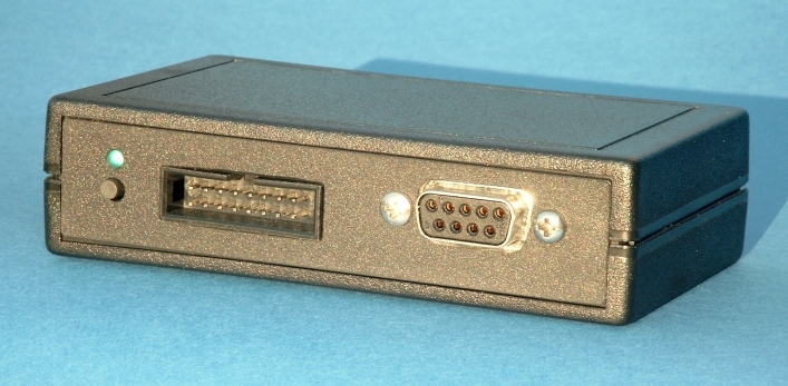
The Monolith in a JM 42-000 case |
|
Non Plagiat I do not want to leave anybody unmentioned even if some people do not suspect that their suggestions influenced this project. By the way, an interesting accumulation of first names starting with the same letter can be observed. Could that mean anything? |
|
The p21 protocol |
|
Jermaine Lewis |
|
The 10nF capacitor in the frontend for an improved CMRR |
|
Jim Peters |
|
Hardware tips on the OpenEEG page |
|
Jörg Hansmann |
|
The basic ModularEEG design |
|
Jörn Walter |
|
During a conversation with him I developed the idea of converting the ModularEEG into the MonolithEEG. |
|
Jarek Foltynski |
|
Bottom Layer |
|
Top Layer |
|
A Testing plug for 333uVpp |
|
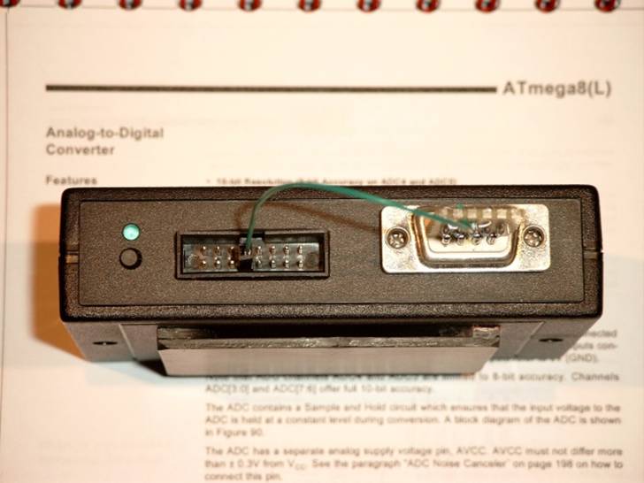
The plugged in testing plug. The 14Hz rectangular voltage at PB1 |
|
Thanks Many thanks to Christoph Veigl for modifying the BrainBay Software to support the MonolithEEG. And also many thanks to Nils Hasler for translating this web page. Many thanks to Silvia for the final inspection and correction. |
|
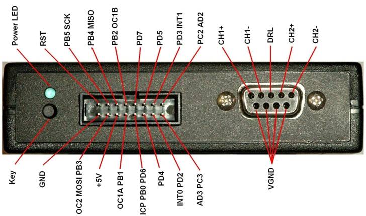
Connection diagram of the MonolithEEG. The six leftmost pins form the ISP connector |
|
Specs I built and assessed three Monoliths version 1.2. The comparison to the simulation (PSPICE) confirmed the achieved measurements. However, it should be noted that the measurement accuracy is low at these very small amplitudes. The measurements were made using a Tektronix TDS2012, a 33120A Hewlett Packard Function Generator and ElectricGuru. |
|
frequency response |
|
Damping of aliasing frequencies |
|
other electrical characteristics |
|
Common mode rejection ratio (CMRR) |
|
The CMRR was measured at 50mVpp, 10Hz over 10k resistors connected to the EEG inputs |
|
Signal to Noise Ratio (SNR) |
|
For measuring the SNR four EEG inputs were each connected via a 10k resistor to the DRL |
|
The CMRR was not measurable against DRL with the available equipment and was thus assumed to be below the noise threshold. |
|
MonolithEEG V1.2 Newer Version 1.3 |
|
Improvements (done in version 1.3) USB: The suspend mode of the USB interface controller is not supported by the MonolithEEG. I have not encounter problems yet but this possibility should not be overlooked. Just because I have not experienced problems with USB does not mean that it works for other people. If you would like to support the suspend function you should insert an additional P-MOSFET into the 5V supply voltage on the USB side. Pin 15 /PWREN of the FTDI232 switches the gate of the MOSFET. Anything that does not belong to the USB interface must pass through this transistor. More information about this can be found in the datasheet of theFTDI232
Frequency response : The layout specifies a second frequency response using different resistors and capacitors. However, this combination still needs to undergo further tests. |
|
Right at the beginning the license agreement should not remain unmentioned. The following should thus be noted: |
|
The ModularEEG allows the replacement of the 6N139 with the faster 6N137. Soley the resistors R125 and R130 on the digital board have to be taken out otherwise both receivers would be disabled permanently. |
|
LOCKBITS |
|
0x3F oder 0xFF
# No memory lock features enabled # Application Protection Mode 1, No lock on SPM and LPM # Boot Loader Protection Mode 1, No lock on SPM and LPM |
|
HFUSE |
|
LFUSE |
|
0xDF |
|
0x3F
# Boot Flash section size = 128 words (not important) # Brown-out detection level at Vcc = 4.0V # Brown-out detection enabled # Ext. Crystal/Resonator High frequ; Start-up time 16K CK + 64ms |
|
EEG input voltage range |
|
±250uV |
|
Maximum offset voltage at 100nA |
|
±140mV |
|
|
|
|
|
Resolution |
|
10 Bit / 0.5uV |
|
Effective resolution |
|
9 Bit |
|
Noise |
|
1uVpp |
|
|
|
|
|
current consumption |
|
75mA |
|
Supply voltage |
|
4.5 - 5.5V |
|
Damping |
#1 |
#2 |
#3 |
Mean |
Simulation |
|
-3dB HP |
0.26Hz |
0.27Hz |
0.26Hz |
0.26Hz |
0.24Hz |
|
-1dB HP |
0.48Hz |
0.49Hz |
0.48Hz |
0.48Hz |
0.44Hz |
|
-1dB LP |
50Hz |
46Hz |
50Hz |
49Hz |
49Hz |
|
-3dB LP |
62Hz |
60Hz |
62Hz |
61Hz |
62Hz |
|
Aliasing frequency |
#1 |
#2 |
#3 |
Mean |
Effective Bits |
Simulation |
Effective Bits |
|
128Hz |
-21.1dB |
-20.9dB |
-20.9dB |
-21dB |
3.8 |
-20.5dB |
3.7 |
|
256Hz |
-51.8dB |
-51.1dB |
-53.3dB |
-52dB |
8.9 |
-42.6dB |
7.4 |
|
300Hz |
-54.5dB |
-53.9dB |
-56.9dB |
-55dB |
9.4 |
-48dB |
8.2 |
|
512Hz |
-77dB |
-77dB |
-77dB |
-77dB |
13 |
-67dB |
11.4 |
|
# |
Measured against VGND |
Measured against DRL |
|
1 |
8uVpp / -76dB |
<1uVpp / <-94dB |
|
2 |
8uVpp / -76dB |
<1uVpp / <-94dB |
|
3 |
8uVpp / -76dB |
<1uVpp / <-94dB |
|
# |
uVpp |
SNR |
|
1 |
1 |
-54 |
|
2 |
1 |
-54 |
|
3 |
1 |
-54 |